When you create a Printed Circuit Board in most cases you want to route the power supply lines with a wider width than normal signal lines. You must do this to reduce the inductance and the power supply lines to obtain a good quality power supply. This no
Using Eagle classes to optimize the routing of power supply lines in your PCB
By Stephane Carrez2007-02-04 21:18:00
In Eagle you can associate a class with a net. The class defines some information for the autorouter to control the width, clearance and drill of vias. By creating a specific class for the ground, the power supply and normal signals, we can control quite easily the width of each signal. The feature is quite hidden in Eagle and I think it is not well explained. First, in the Eagle board editor, activate the class editor. To my knowledge, the only way to activate it is by typing the command:
class
in the command window. This will open the dialog box: 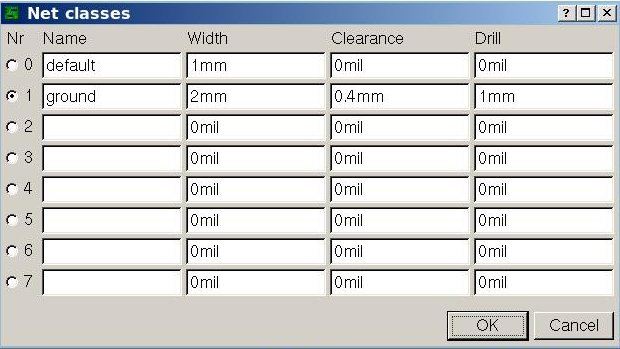
where you can control all the parameters. Then, once the classes are defined, we just need to assign the class to the nets that we want. This is done easily by using the Eagle menus. Select the Change toolbar, and choose Class. Then, click on the nets that you want to assign the selected class.
In the PCB layout below, the ground lines was assigned the Ground class with a width of 2 mm and others have a width of 1mm. The reason why the ground is larger is that it must hold the return current of several power lines. This PCB is a simple power supply rectifier board.
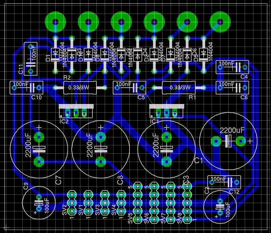
The clearance defines the minimum space between the signal and other signals. Specifying a large clearance reduce the capacity between two adjacent signals because the space between them will be larger. For an electronics hobbyist, it is also important to have large clearance because it makes a PCB that is easier to create (I have found that using a clearance of less than 0.2mm makes the PCB very hard to create due to the very short distance between signals). Using a large clearance has a serious drawback: it can make the routing impossible. Note that the above PCB does route at 100%. In fact, 3 signals are not routed!
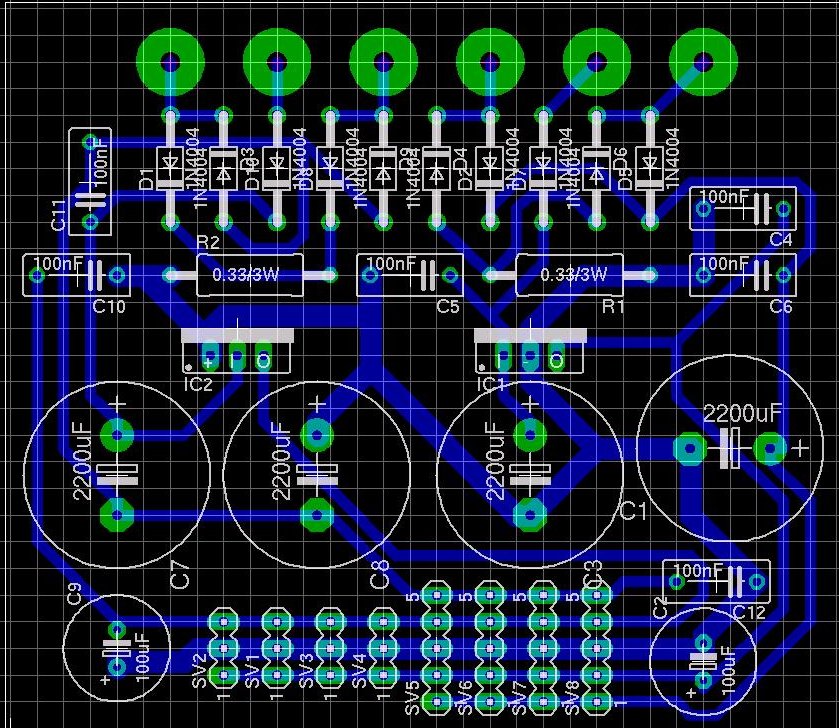
By editing the default class used by the power supply lines and specifying a clearance of 0.6mm, the auto router creates the routes in a different manner and it succeeds to route all of them!
Tags
- Facelet
- NetBSD
- framework
- Mysql
- generator
- firefox
- application
- interview
- ReadyNAS
- Security
- binutils
- ELF
- JSF
- Java
- bacula
- Tutorial
- Apache
- COFF
- collaboration
- planning
- project
- upgrade
- AWA
- C
- EL
- J2EE
- UML
- php
- symfony
- Ethernet
- Ada
- FreeBSD
- Go
- KVM
- MDE
- Proxy
- STM32
- Servlet
- backup
- lvm
- multiprocessing
- web
- Bean
- Jenkins
- release
- OAuth
- ProjectBar
- REST
- Rewrite
- Sqlite
- Storage
- USB
- Ubuntu
- bison
- cache
- crash
- Linux
- gcc
- performance
- lex